
All module manuals in one convenient place!
This module is an 8-step tempo sequencer.
(1) Reset – Resets sequence to first step
(8) BPM – Sets the tempo of the current step
(9) Hold – Sets the amount of beats made before moving to the next step
(2) Sequence Steps – Indicate the output step, active steps, and innactive steps
Output Step: bright green light
Active Step: dim green light
Innactive Step: off light
(3) Edit Steps – Indicate which step's values are being edited
(4) Reset – Resets sequence to first step
(5) On/Off – Turn edit step on or off
(6) Up – Move edit step up
(7) Down – Move edit step down
(A) Clock – Outputs clock pulse of sequence steps
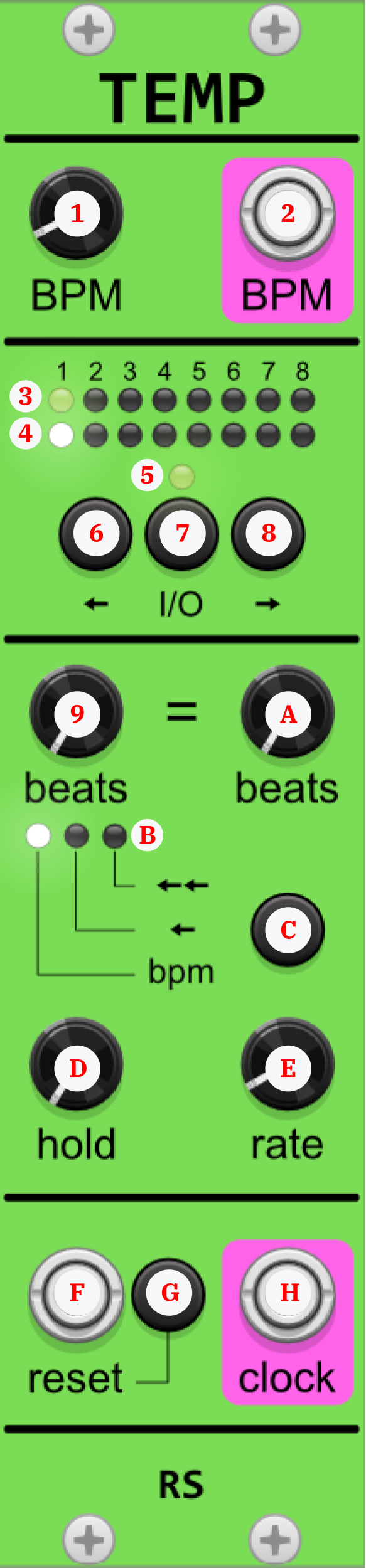
This module is a dynamic 8-step tempo sequencer that serves as an expansion of Tempinator. Each step's tempo can depend upon a previous step's tempo. In other words, it implements metric modulation.
For the purposes of understanding tempo relationships, think of the following: the duration of x beats of the new tempo is the same as y beats of the dependence tempo.
(F) Reset – Resets sequence to first step
(1) BPM – Sets the master tempo of the module. It is the same for each step
(9) Beats of Dependent Tempo – Sets the number of dependence tempo beats
(A) Beats of New Tempo – Sets the number of new tempo beats
(D) Hold – Sets the amount of beats made before moving to the next step
(E) Rate – Fine tunes the speed of the tempo
(3) Sequence Steps – Indicates the output step, active steps, and innactive steps
Output Step: bright green light
Active Step: dim green light
Innactive Step: off light
(4) Edit Step – Indicates which step's values are being edited
(5) On/Off – Indicates the state of the edit step
(B) Dependence – Indicates which dependence mode is selected
(6) Left – Move edit step to the left
(7) On/Off – Turn edit step on or off
(8) Right – Move edit step to the right
(C) Dependence Selector – Choose what beats the new tempo depends on
BPM: Depends on master tempo
←: Depends on previous tempo, even if inactive
←←: Depends on previous previous tempo, even if inactive
(G) Reset – resets sequence to first step
(2) BPM – Outputs clock pulse of master tempo
(H) Clock – Outputs clock pulse of sequence steps
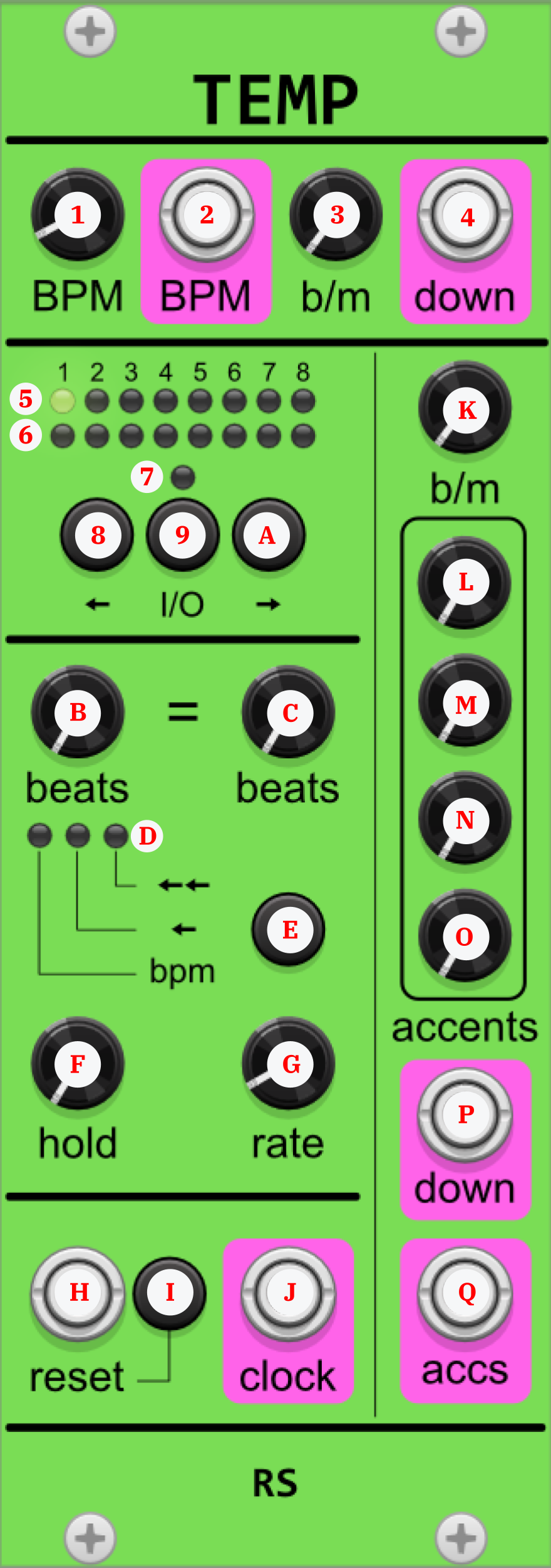
This module is an 8-step tempo sequencer that combines Tempinator_Dependence and Accent to allow the characteristics of each step's tempo to be fully realized.
(H) Reset – Resets sequence to first step
(1) BPM – Sets the master tempo of the module. It is the same for each step
(3) Master Beats per Measure – Sets the number of master tempo beats between each downbeat. For example, if the tempo should reflect 5/4, set b/m to 5.
(B) Beats of Dependent Tempo – Sets the number of dependence tempo beats
(C) Beats of New Tempo – Sets the number of new tempo beats
(F) Hold – Sets the amount of beats made before moving to the next step
(G) Rate – Fine tunes the speed of the tempo
(K) Beats per Measure – Sets the number of step tempo beats between each downbeat. For example, if the tempo should reflect 5/4, set b/m to 5.
(L-O) Accents – Set the beats to accent during each measure
(5) Sequence Steps – Indicates the output step, active steps, and innactive steps
Output Step: bright green light
Active Step: dim green light
Innactive Step: off light
(6) Edit Step – Indicates which step's values are being edited
(7) On/Off – Indicates the state of the edit step
(D) Dependence – Indicates which dependence mode is selected
(8) Left – Move edit step to the left
(9) On/Off – Turn edit step on or off
(A) Right – Move edit step to the right
(E) Dependence Selector – Choose what beats the new tempo depends on
BPM: Depends on master tempo
←: Depends on previous tempo, even if inactive
←←: Depends on previous previous tempo, even if inactive
(I) Reset – Resets sequence to first step
(2) BPM – Outputs clock pulse of master tempo
(4) Master Downbeat – Outputs downbeat of the hypothetical measure set by b/m
(J) Clock – Outputs clock pulse of sequence steps

(P) Step Downbeat – Outputs downbeat of the hypothetical measure set by b/m
(Q) Accents – Outputs accents
This module treats the input pulse with a specific time signature. The user can output the downbeat of the time signature, and specify accents on other beats as well.
(1) Pulse – A clock pulse, or any other signal for that matter. A pulse is 'counted' when the input strength is greater than 0V
(2) Beats per Measure – Sets the time signature length
(3-6) Accents – Set the beats to accent during each measure
(7-A) Accents – Indicates when the beat signified by the accent knob is being output
(B) Downbeat – Outputs the downbeat of the time signature
(C) Accents – Outputs clock pulse of sequence steps

This module is an expansion of Accent which adds individual outputs for each accent.
(1) Pulse – A clock pulse, or any other signal for that matter. A pulse is 'counted' when the input strength is greater than 0V
(2) Beats per Measure – Sets the time signature length
(A-G) Accents – Set the beats to accent during each measure
(3-9) Accents – Indicates when the beat signified by the accent knob is being output
(H-N) Individual Accents – Output the signals of each individual accent
(O) Downbeat – Outputs the downbeat of the time signature
(P) Accents – Outputs clock pulse of sequence steps

This module sets an occurance limit on three signals. If one signal reaches its limit, it won't be output again until the other two signals have reached their limits.
To set this module to two-signal balance mode, set Knob (9) to 0.
(4-6) Signal – A clock pulse, or any other signal for that matter. A pulse is 'counted' when the input strength is greater than 0V
(7-9) Beats per Measure – Set the occurance limit of each signal
(1-3) Limit Indicator – Indicates when a signal has reached its occurance limit
(A-C) Signal – Output each signal as long as their respective limit has not been reached.
This module is a pulse-programmable gate. The user can adjust the amount of time the gate stays closed and open based on a specified number of pulses.
(1) Pulse – A clock pulse, or any other signal for that matter. A pulse is 'counted' when the input strength is greater than 0V
(2) Reset – Closes the gate and resets the pulse count
(4) In – Signal to be passed through an open gate
(5) Closed Wait – Amount of pulses the gate remains closed for
(7) Open Wait – Amount of pulses the gate remains open for. Setting this knob to zero means the gate will never close once opened
(3) Closed – Indicates the gate is closed
(6) Open – Indicates the gate is open
(8) Out – Outputs In signal when gate is open
This module is a modification of WaitGate. There is no input pulse. Instead, pulses depend on the In signal having a strength of 0V.
(2) Reset – Closes the gate and resets the pulse count
(4) In – Signal to be passed through an open gate. Pulses are counted when the signal has a strength of 0V
(5) Closed Wait – Amount of pulses the gate remains closed for
(7) Open Wait – Amount of pulses the gate remains open for. Setting this knob to zero means the gate will never close once opened
(1) Zero – Indicates when the In signal has a strength of 0V
(3) Closed – Indicates the gate is closed
(6) Open – Indicates the gate is open
(8) Out – Outputs In signal when gate is open
This module is a modification of WaitGate. It implements three reset options.
(1) Master Reset – Resets gate to closed and pulse count to zero
(2) Closed Reset – Resets closed pulse count to zero. Only has an effect if the gate is closed
(3) Open Reset – Resets open pulse count to zero. Only has an effect if the gate is open
(4) Pulse – A clock pulse, or any other signal for that matter. A pulse is 'counted' when the input strength is greater than 0V
(6) In – Signal to be passed through an open gate
(7) Closed Wait – Amount of pulses the gate remains closed for
(9) Open Wait – Amount of pulses the gate remains open for. Setting this knob to zero means the gate will never close once opened
(5) Closed – Indicates the gate is closed
(8) Open – Indicates the gate is open
(A) Out – Outputs In signal when gate is open
This module is a modification of WaitGate. To open and close, two signals must meet their wait requirements.
(1) Reset – Resets gate to closed and pulse count to zero
(3, 4) Pulses – A clock pulse, or any other signal for that matter. A pulse is 'counted' when the input strength is greater than 0V
(8, 9) In – Signals to be passed through an open gate
(A, B) Closed Waits – Set the count required from each pulse before the gate opens
(F, G) Open Waits – Set the count required from each pulse before the gate closes. Setting either of these knobs to zero means the gate will never close once opened
(5, 7) Closed Count Met – Indicates when a pulse has met its closed wait requirement
(6) Closed – Indicates the gate is closed
(C, E) Closed Count Met – Indicates when a pulse has met its open wait requirement
(D) Open – Indicates the gate is open
(H, I) Out – Outputs In signal when gate is open
This module is a multi-trigger flipflop.
(3) In – Signal to be flipped or flopped
(4-7) Triggers – Signals to change state of flipflop when they have a strength greater than 0V
(1) Flip – Indicates when the Flip state is active
(9) Flop – Indicates when the Flop state is active
(2) Flip Out – Outputs In signal when Flip state is active
(8) Flop Out – Outputs In signal when Flop state is active
This module is a derrivation of FlipFlop where triggers are assigned a specific state (Flip or Flop).
(3, 4) Flip Triggers – Signals to change state to Flip when they have a strength greater than 0V
(5) In – Signal to be flipped or flopped
(6, 7) Triggers – Signals to change state to Flop when they have a strength greater than 0V
(1) Flip – Indicates when the Flip state is active
(9) Flop – Indicates when the Flop state is active
(2) Flip Out – Outputs In signal when Flip state is active
(8) Flop Out – Outputs In signal when Flop state is active
This module is a derrivation of FlipFlop where two inputs are flopped into one output.
(1-4) Triggers – Signals to change state of flip-flop when they have a strength greater than 0V
(5) Flop In – Signal to be output when Flop state is active
(9) Flip In – Signal to be output when Flip state is active
(6) Flop – Indicates when the Flop state is active
(8) Flip – Indicates when the Flip state is active
(2) Out – Outputs one of the two In signals depending on the state of the flip-flop
This module is a derrivation of FlopFlip where triggers are assigned a specific state (Flop or Flip).
(1) Flop In – Signal to be output when Flop state is active
(2, 3) Flop Triggers – Signals to change state to Flop when they have a strength greater than 0V
(7, 8) Flip Triggers – Signals to change state to Flip when they have a strength greater than 0V
(9) Flip In – Signal to be output when Flip state is active
(4) Flop – Indicates when the Flop state is active
(6) Flip – Indicates when the Flip state is active
(5) Out – Outputs one of the two In signals depending on the state of the flip-flop







